How to Put Zircon Stud Finder Back Together: Easy Repair Guide
If you are trying to figure out how to put Zircon stud finder back together, start by removing the battery, identify where the circuit board, sensor assembly, buttons, battery contacts, and any small springs or plastic pieces fit, then seat those parts in the molded guides inside the housing before carefully closing the two case halves. Do not force the housing closed. If the case will not sit flush, an internal component is probably out of position.
The exact internal arrangement varies between Zircon models. A simple StudSensor may contain only a circuit board, sensing components, button mechanism, LEDs, and battery contacts, while a MultiScanner or more advanced model may have additional switches, displays, light pipes, or sensor components. Because of those differences, there is no single internal layout that applies to every Zircon stud finder.
Fortunately, most handheld stud finders use a molded plastic case that makes correct component placement easier to identify. The circuit board generally rests in locating posts or channels, buttons align with switches on the board, battery terminals fit into dedicated slots, and the sensing area must sit flat against the front or back of the housing. Reassembly becomes much easier if you work slowly and understand what each loose piece does.
In this guide, I’ll explain how to put a Zircon stud finder back together step by step, how to identify common internal parts, what to do if a spring or button fell out, how to close the housing without damaging the electronics, and how to test the stud finder after reassembly.
Before You Put a Zircon Stud Finder Back Together

The first step is to avoid creating a second problem while trying to fix the first one.
Remove the battery before touching the internal electronics. This reduces the chance of accidentally powering the circuit while parts are misaligned and also makes the housing easier to handle.
Work on a clean, well-lit table. A light-colored towel or sheet of paper underneath the stud finder is helpful because tiny screws, springs, contacts, or plastic button pieces are easier to see.
If you still have every loose component, do not immediately start snapping pieces together. First examine the inside of both housing halves.
Manufacturers mold supports directly into plastic housings, so you will often see:
- Small posts that support the circuit board.
- Narrow slots for battery contacts.
- Recesses for buttons.
- Channels for wiring or conductive strips.
- Screw posts that pass through the board or around it.
These shapes are useful clues.
Also look at any marks left by the parts themselves. A circuit board that has been installed for years may leave clean contact areas on plastic supports. Springs and metal terminals may leave small polished areas where they previously rested.
If the stud finder was working before the housing came apart, your goal is normally to restore the original alignment rather than modify anything.
Identify the Zircon Stud Finder Model First
Before reassembly, look for the exact model number.
It may be printed on:
- The front label.
- Rear housing.
- Battery compartment.
- Product identification sticker.
Zircon has produced many stud-finder designs, including basic StudSensor models and multifunction scanners. Their housings and internal controls are not necessarily interchangeable.
Knowing the exact model is especially helpful if several components fell out at once.
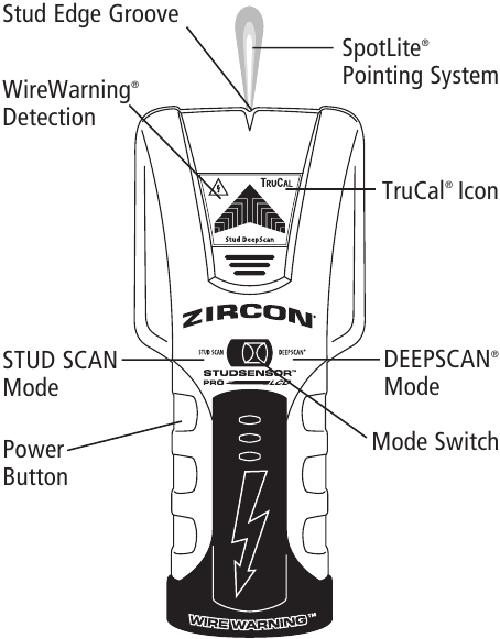
For example, one model may use a side-mounted activation button while another uses a front button. Some models have separate mode switches, displays, SpotLite indicators, or additional sensing circuitry.
If your internal layout looks different from a general reassembly guide, trust the physical locating points in your specific case rather than forcing parts into a position that seems typical.
Key Takeaways:
- Remove the battery before beginning reassembly.
- Identify the exact Zircon model whenever possible.
- Use molded slots, posts, and recesses inside the case as placement guides.
- Never force the housing shut when something does not line up.
Parts You May Find Inside a Zircon Stud Finder
A Zircon stud finder is usually less mechanically complicated than it first appears.
Most of the important functions are mounted to one circuit board.
Circuit Board
The printed circuit board, or PCB, is the main electronic assembly.
It may carry:
- Sensors.
- LEDs.
- Push-button switches.
- Display components.
- Processor electronics.
- Battery connections.
- Mode-selection components.
The board normally sits in molded plastic supports inside the housing.
It should generally lie flat rather than rocking from side to side.
Sensor Area
The sensing components are usually positioned so that they remain at a specific distance from the wall-facing side of the stud finder.
That spacing is important.
If the board or sensor sits crooked after reassembly, the stud finder may calibrate poorly or give inconsistent results.
Do not add homemade padding, tape, or spacers unless you are replacing something that was clearly present originally.
Activation Button
Many Zircon stud finders have a button that mechanically presses an electronic switch on the circuit board.
If the outer button falls out when the housing is opened, it can be easy to reinstall backward.
Look for a small projection on the inner side of the plastic button. That projection normally points toward the electronic switch it needs to press.
When correctly positioned, the button should move freely without falling inward.
Battery Contacts
Battery terminals are one of the parts most likely to shift during disassembly.
Depending on the design, you may have metal spring contacts, clips, or terminals connected to the board.
They must align correctly with the battery compartment.
A bent terminal may prevent the stud finder from powering on even if everything else is assembled correctly.
Indicator Light Pieces
Some stud finders use a transparent or translucent plastic piece to carry light from an LED on the circuit board to the outside of the housing.
This is sometimes called a light pipe or light guide.
If one falls out, it normally fits between the board’s LED and a window in the housing.
Because these pieces can be nearly transparent, they are easy to overlook.
Springs or Small Metal Pieces
Some versions may contain springs or metal components associated with buttons, battery contacts, or switches.
Do not guess that every small metal piece is a battery terminal.
Before installing it, look for a matching molded pocket or contact point.
How to Put Zircon Stud Finder Back Together Step by Step
If the housing has already been opened and the pieces are loose, the following sequence works for many simple electronic stud finders.
1. Remove the Battery
Take the battery completely out of the unit.
Do not attempt to assemble the housing with the battery installed.
If the battery is old, leaking, swollen, or corroded, replace it rather than reinstalling it.
Also inspect the battery terminals for corrosion before continuing.
2. Separate and Identify All Loose Pieces
Place the two housing halves beside each other.
Then place the circuit board, screws, buttons, springs, and other parts where you can see them.
Do not stack loose pieces.
Look carefully for tiny transparent plastic parts because they can be difficult to notice.
At this stage, you should be able to determine whether something appears broken rather than simply disassembled.
A cracked button, snapped screw post, broken circuit board, or detached electronic component may require repair beyond normal reassembly.
3. Choose the Housing Half That Holds the Circuit Board
One side of the case will normally have the clearest supports for the electronics.
You may see several molded posts surrounding the expected board shape.
Lay that housing half flat on the table.
Do not immediately install the circuit board if buttons or light guides need to go underneath it.
4. Reinstall the External Buttons First
If an activation button or selector fell out, place it into the opening from the inside of the housing.
The finished outer surface of the button should face outward.
The small projection or actuator normally points inward toward the circuit-board switch.
Press the button gently with your finger.
It should move in and out without binding.
If it immediately falls out or sits crooked, rotate it and inspect the molded guides.
5. Reinstall Any Light Guide or Indicator Window
If you found a clear plastic piece, identify which indicator opening it fits.
A light guide normally rests between an LED and the exterior indicator window.
Its shape often makes orientation obvious once you compare it with the plastic housing.
Do not glue it in place unless you know it was originally glued.
Glue can cloud transparent plastic or prevent the housing from fitting correctly.
6. Position the Battery Contacts
Look inside the battery compartment and identify where each terminal needs to appear.
Metal contacts normally fit into narrow molded channels.
Make sure they cannot rotate when the case is closed.
If a terminal is slightly bent, do not repeatedly flex it. Thin spring metal can fatigue and break.
The contact should make firm contact with the battery but should not be crushed when the housing closes.
7. Seat the Circuit Board
Carefully lower the PCB into the housing.
Do not press down hard.
It should naturally settle onto its supports.
Check several things before moving on.
The activation button should align with its board switch. LEDs should line up with their windows or light guides. Battery connections should point toward the battery compartment. The sensing area should sit properly against its intended side of the case.
Gently press the external activation button.
You should feel it contacting the switch on the board.
If the button does nothing or feels permanently depressed, the board or button is probably misaligned.
8. Check for Foam Pads or Spacers
Some electronic tools use small foam pads or insulating pieces to keep the board stable.
If one fell out, look for a rectangular recess or an area where its shape clearly matches the case.
A spacer can be important because it prevents the circuit board from moving after the housing is tightened.
Do not replace a missing spacer with a random thick material. Changing the position of the sensor relative to the wall-facing surface can affect performance.
9. Make Sure No Parts Cross the Screw Posts
Before installing the second housing half, look at every screw post.
Nothing should cross underneath or over a post unless the original design clearly requires it.
A misplaced metal terminal or board edge can be crushed when the screw is tightened.
Also make sure no component protrudes above the plastic housing rim.
10. Fit the Second Housing Half Without Screws
This is one of the most important steps.
Place the second half of the case on top and gently bring the halves together.
Do not install screws yet.
The housing should close with minimal pressure.
A very small gap may disappear when the screws are installed, but a large gap means something is incorrectly positioned.
If the case rocks, springs open, or requires significant squeezing, open it again.
The usual causes are:
- Misaligned button.
- Circuit board outside its locating posts.
- Battery terminal out of position.
- Light guide sitting incorrectly.
- Wire or contact caught between case halves.
Never solve a large gap by tightening the screws harder.
You can crack the housing or circuit board.
11. Install the Screws Gradually
Once the housing sits together correctly, reinstall the case screws.
Start every screw before fully tightening any one of them.
Then tighten them gradually.
Use only enough torque to hold the housing securely.
Stud-finder housings are plastic, and overtightening can strip the screw posts.
If one screw suddenly spins without tightening, the plastic threads may already be damaged.
12. Reinstall the Battery
After the case is fully assembled, install the correct battery.
Make sure polarity is correct.
Close the battery compartment and check that nothing feels loose inside the device.
How to Tell Whether the Internal Parts Are Positioned Correctly
You can perform several checks before actually scanning a wall.
First, shake the stud finder very gently.
You should not hear major components rattling inside.
A tiny amount of button movement may be normal, but a circuit board should not sound loose.
Next, press the activation button.
It should feel similar to a normal electronic switch. It should not remain stuck down or require excessive force.
Then turn on or activate the stud finder according to its normal operating procedure.
The indicators should behave normally.
If the device does not power on, remove the battery and recheck the battery terminals before reopening the entire unit.
Key Takeaways:
- Install loose buttons and light guides before seating the circuit board when their position requires it.
- The PCB should rest naturally in its molded supports.
- Test-fit the housing before inserting screws.
- If the case needs force to close, something inside is incorrectly positioned.
What If the Zircon Stud Finder Will Not Turn On After Reassembly?
Failure to power on does not automatically mean the electronics were damaged.
Battery contact problems are very common after a device has been opened.
Remove the battery and inspect both terminals.
Make sure neither contact was pushed behind the plastic battery compartment when the case closed.
Check battery polarity as well.
If you have another known-good battery of the correct type, try it.
Then inspect the activation button.
The external button may appear normal while failing to reach the small electronic switch on the PCB.
If pressing different parts of the outer button changes the behavior, its alignment may be incorrect.
If the device worked before disassembly but remains completely dead after these checks, reopen it and inspect the circuit board for a disconnected terminal or damaged solder joint.
Avoid touching or bending components unnecessarily.
What If the Button Is Stuck?
A stuck activation button almost always indicates an alignment problem.
The plastic button may be rotated incorrectly, the circuit board may be sitting too high, or the two housing halves may be squeezing the button.
Remove the battery first.
Loosen the case screws slightly and test the button.
If the button suddenly moves properly, something inside is being compressed when the case is tightened.
Open the housing and reposition the button and circuit board.
Do not sand or cut the button simply because it sticks after reassembly. If it worked previously, its original shape is probably correct.
What If a Spring Fell Out?
This can be one of the more confusing reassembly problems because a small spring does not always make its purpose obvious.
Start by examining the battery compartment.
Battery contacts are common locations for spring-like pieces.
Then inspect the activation and mode-selector mechanisms.
Look for a round recess, narrow slot, or small peg that matches the diameter of the spring.
Do not randomly place the spring underneath the circuit board.
A metal spring touching the wrong electronic contacts could cause a short circuit.
If you cannot determine its original location confidently, identifying the exact Zircon model becomes particularly important before powering the unit again.
What If the Circuit Board Fell Completely Out?
A loose circuit board looks alarming, but it is often straightforward to reposition if no wires or components broke.
Hold the board only by its edges when practical.
Avoid scraping the sensing components or touching exposed electronics more than necessary.
Match the board shape to the supports inside the housing.
Useful orientation clues include the locations of the activation switch, indicator lights, display, and battery connection.
For example, if a push switch is near one edge of the PCB, that edge should align with the external activation button.
Similarly, LEDs should point toward their corresponding openings.
When the board is correctly oriented, it will normally sit far more naturally than when reversed.
What If the Two Case Halves Will Not Close?
Do not tighten the screws to pull them together.
Open the case again and inspect the edges.
A common cause is the circuit board being slightly outside one locating tab.
Even a difference of a fraction of an inch can prevent the case from closing.
Battery contacts are another frequent cause.
A spring terminal that should enter a narrow slot may instead become trapped between the housing halves.
Check the button mechanism as well.
If the button protrudes too far inward, it may prevent the board or opposite housing half from seating.
The correct assembly should close with very little force.
How to Test the Zircon Stud Finder After Reassembly
Powering on is only the first test.
A stud finder can turn on while still having a sensor or board positioned incorrectly.
Use a wall where you already have a reasonable idea of the stud location.
Start with a standard interior drywall wall rather than a difficult surface such as tile, fiberglass, plaster, or thick paneling.
Operate the stud finder according to its normal calibration procedure.
Then scan slowly across the suspected stud from both directions.
You should get repeatable readings.
If the stud location changes dramatically every time, reopen the device and make sure the board and sensor area are seated flat.
Compare Several Known Studs
One successful reading is useful, but several are better.
Try locating multiple studs on the same wall.
If their spacing and detected centers are reasonable and repeatable, the stud finder is probably functioning normally.
If it detects the entire wall as a stud, constantly flashes an error, or refuses to calibrate, something may still be misaligned.
Calibration Problems After Reassembly
Many electronic stud finders calibrate based on what they sense when activated against the wall.
Reassembly can interfere with that process if the sensor is no longer held in its original position.
Potential causes include a PCB that is tilted, missing spacer, incorrectly installed housing part, or case that is not fully closed.
Before assuming the electronics are permanently damaged, check the mechanical fit again.
Also make sure you are using the tool correctly.
Place it flat against the wall, start calibration in an area that is unlikely to be directly over a stud, and keep the tool flat while scanning.
The exact operating procedure varies by model, so the instructions for your Zircon model should take priority.
Can You Glue a Broken Zircon Stud Finder Case Back Together?
It depends on what broke.
A small cosmetic crack away from buttons, sensors, battery contacts, and screw posts may be repairable.
A damaged structural screw post is more complicated because the case needs to hold the circuit board at the correct position.
I would avoid putting glue anywhere near:
- The sensor face.
- Circuit board.
- Activation switch.
- Battery terminals.
- Indicator windows.
- Housing seams that must be reopened.
Excess adhesive can spread into the electronics or permanently lock the case shut.
If the damage prevents the PCB from sitting securely in its original position, replacement may be more practical than attempting a structural repair.
Should You Repair or Replace the Stud Finder?
Simple reassembly is worthwhile when the device merely came apart and nothing is broken.
Replacement becomes more reasonable when you find:
- Cracked circuit board.
- Broken electronic components.
- Severe battery corrosion.
- Missing proprietary internal parts.
- Broken sensor assembly.
- Housing damage that prevents proper sensor alignment.
Basic electronic stud finders are precision sensing devices despite their simple appearance. A repair that leaves the sensor in the wrong position may produce inaccurate readings even though the device turns on.
When accuracy becomes questionable, especially before drilling near plumbing or electrical wiring, replacement is safer than relying on an unreliable detector.
Key Takeaways:
- Powering on does not prove the stud finder is reading correctly.
- Test it on a normal wall with known or predictable stud locations.
- Repeated calibration errors may indicate internal misalignment.
- Replace the unit if structural or electronic damage makes reliable sensing uncertain.
Common Mistakes When Reassembling a Zircon Stud Finder
One common mistake is opening the housing with the battery still installed.
Another is allowing loose buttons and indicator pieces to fall out without noting their orientation.
The most damaging mistake, however, is forcing the housing together.
Plastic screw posts can easily crack, and the circuit board can be pinched between case halves.
Another frequent problem is overtightening screws. The screws normally thread into plastic posts rather than metal nuts, so very little torque is needed.
Be especially careful with battery contacts. If one is trapped behind plastic or bent away from the battery, the entire unit can appear dead.
Finally, do not add washers, thick tape, random foam, or other spacers to stop rattling unless you know something is missing. Changing the distance between the sensor and the wall-facing surface can potentially affect scanning performance.
FAQs about How to Put Zircon Stud Finder Back Together
How do I put my Zircon stud finder back together?
Remove the battery, place loose buttons and indicator pieces into their housing recesses, position the battery contacts, seat the circuit board in its molded supports, test-fit the opposite case half, and reinstall the screws only after the case closes naturally.
Which way does the Zircon stud finder circuit board go?
Use the controls as orientation guides. The electronic push switch should align with the external activation button, LEDs should align with their indicator windows, and battery connections should face the battery compartment.
The correctly oriented board should also fit naturally into the molded supports.
Why won’t my Zircon stud finder close after I took it apart?
An internal piece is probably out of position.
Common causes include a misaligned circuit board, displaced battery terminal, incorrectly installed button, misplaced light guide, or component caught between the housing halves.
Do not use the screws to force the case closed.
Why won’t my Zircon stud finder turn on after putting it back together?
Start with the battery and battery contacts.
A terminal may have moved during reassembly.
Also verify that the external activation button actually presses the electronic switch on the circuit board.
If those items are correct, inspect the PCB for physical damage.
How do I reinstall the button on a Zircon stud finder?
Place the button into its housing opening from the inside. The exterior face points outward, while the internal actuator normally points toward the push switch on the circuit board.
The button should move freely after the board is installed.
Where does the spring go in a Zircon stud finder?
That depends on the exact model and the shape of the spring.
Check the battery terminals and button or switch mechanisms for a matching mounting location.
Do not place a loose metal spring near the circuit board unless you are confident of its original position.
Can I use glue inside my Zircon stud finder?
I would generally avoid it.
Glue can interfere with buttons, sensing components, battery contacts, and future servicing.
Most internal parts are designed to stay in position through molded housing supports and the pressure of the assembled case.
Can taking a stud finder apart ruin its calibration?
Simply opening the housing does not necessarily ruin the device, but incorrect reassembly can change the position of the sensing electronics.
After reassembly, test the stud finder on a normal wall and confirm that it provides repeatable results.
Why is my Zircon stud finder detecting studs everywhere after reassembly?
The sensor or circuit board may not be seated correctly.
Other possibilities include incorrect calibration technique, low battery voltage, wall conditions, or internal damage.
Test the device on a simple drywall surface before assuming the wall is causing the problem.
Why does my Zircon stud finder beep constantly after I put it together?
Continuous beeping may indicate an activation button being held down, improper calibration, sensor misalignment, low battery condition, or an internal issue depending on the model.
Check whether the button is physically stuck before investigating anything more complicated.
How tight should the Zircon stud finder screws be?
Only tight enough to hold the housing securely together.
Do not overtighten them.
The screws usually fasten into molded plastic posts that can strip or crack under excessive force.
What should I do if a plastic screw post broke?
If the housing still holds together securely and the internal electronics remain correctly positioned, a minor damaged post may not immediately prevent operation.
However, if the broken post allows the circuit board or sensor to move, I would consider replacing the stud finder rather than trusting potentially inconsistent readings.
Can I test the stud finder without putting all the screws back?
You may be tempted to test the electronics with the housing open, but final scanning accuracy should be evaluated only after the case is correctly assembled.
The housing helps position the sensor at its intended distance from the wall.
What if I lost one of the internal parts?
Do not substitute a random spring, spacer, or metal part unless you know exactly what was lost.
Identify the model and determine what the missing component does. If it affects sensor positioning, battery connection, or controls, replacement of the tool may be more practical.
Conclusion
Learning how to put Zircon stud finder back together is usually straightforward when the device simply came apart and none of the electronic components were damaged. Remove the battery first, identify every loose part, reinstall the buttons and battery contacts, seat the circuit board in its molded supports, and make sure all switches and indicator lights align with the housing.
The most important rule is not to force anything. A correctly assembled Zircon stud finder should allow its case halves to come together with very little pressure. If there is a large gap, reopen the unit and find the misplaced component rather than tightening the screws harder.
After the housing is assembled, install the battery and test the device on a simple drywall wall. Confirm that it powers on, calibrates normally, and identifies several stud locations consistently from repeated scans.
If the stud finder worked before disassembly but will not turn on afterward, I would check the battery terminals and activation-button alignment first. If it powers on but gives wildly inconsistent readings, inspect the circuit-board and sensor positioning.
And if the circuit board, sensor components, or housing supports are seriously damaged, replacing the tool is safer than trusting questionable readings—particularly when you are using the stud finder to avoid hidden electrical wiring or plumbing before drilling.